EBL Battery Technology for Licensing
EBL is offering its battery Technology through the company MEC INC. if anyone wants to license the Technology… for more information email nt@energybat.com
MEC Inc. Battery Charger Patent

Copyright© March 2021, Karl Zimmer, All rights reserved
EBL Lab Overview
Located near the city of Philadelphia, this physics and electrical research lab has been prototyping designs for 39 years. The almost singular focus has been on alternative energy generation for off-grid usage. Using exceptional theory/patent/design interpretations, technological devices have been built and remodeled showing off some of the finer recreations of work by Bearden, Bedini, Tesla, Newman, and others who work quietly in the background. The physical modeling of the devices and data collection of the electrically generated empirical evidence are first-rate. Devices have been created that push into the new physics territories of applied electrical principles and take it to new heights.
Shown below is a brief list of the most recent devices and technologies developed. Using easily accessible parts as a prime foundational perspective, Mr. Miller and his associates have shown that improved designs of traditional technologies can raise the known efficiencies of rotational generators and battery storage systems to new levels.
- Water Turbine – A self-contained, pressurized, closed-loop forced water electrical generator that takes advantage of flowing water phase shifting.
- Air Turbine – Easily the most efficient wind turbine design seen thus far. Inexpensive, bird-safe, highly efficient in low to moderate wind speeds.
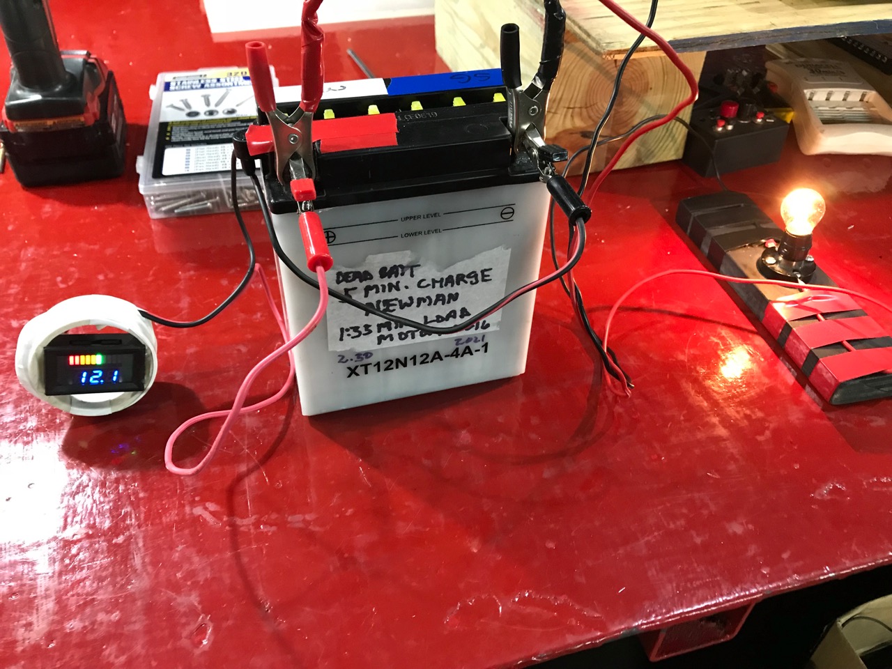
- Pulsed Battery Charging up to 150 Amps – This is the high current battery charger that the Electrical Vehicle market has been looking for. This technology works so well that it maintains the batteries to their near-new state for thousands of charges and still delivers recharges in record time.
- Bedini Charger – An improved version of this lead-acid technology that started a small revolution in the re-charging industry.
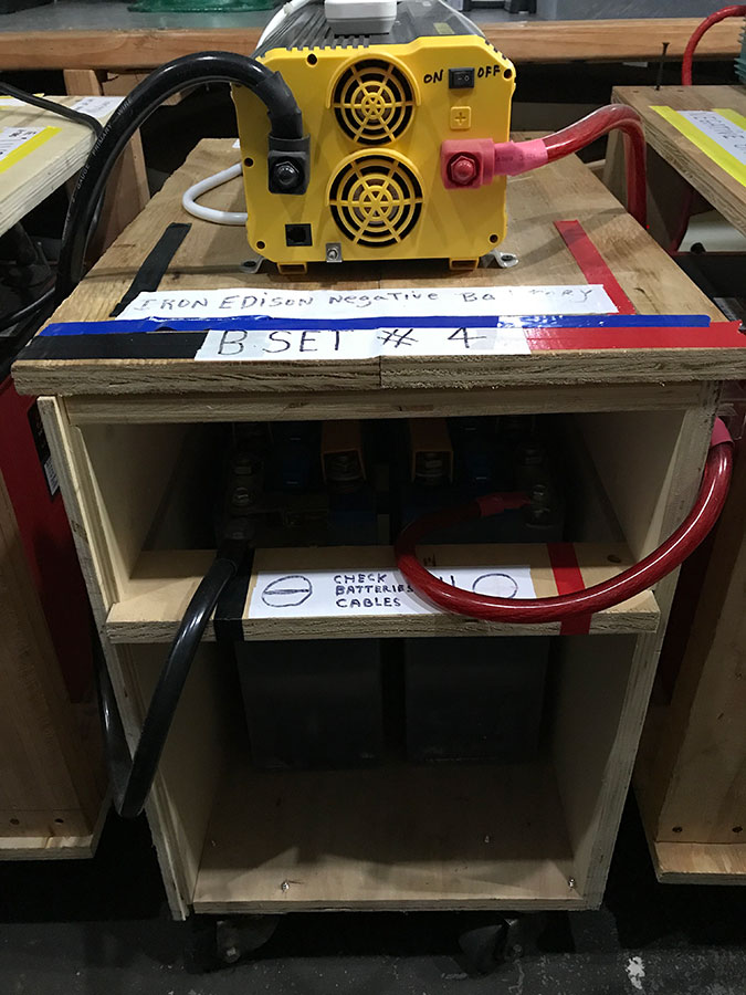
- Large magnetic motor system that consumes virtually no electrical battery power – This generating system produces large amounts of electrical current with just a dozen 12-volt batteries with their voltages purposely run down. This will stretch your knowledge of electrical engineering.
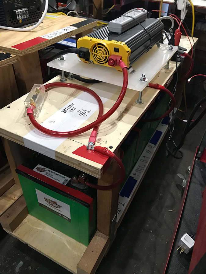
- Three battery charge system – A charging and battery rotation system that keeps the batteries in tip top form. This shows how exercising a battery’s voltage/current parameters with rest states programmed in the cycle can improve battery performance dramatically.
- Efficient Mobile Storage Unit – This patented, back-of-the-truck or Humvee storage unit is multi-facetted, rollable and removable. It brings better stowage capacity, organization, and safety to anyone who drives a 4×4 truck.
- Broad Spectrum Plasma Reactor – This is a scalable dynamic plasma-charged device that has applications to internal combustion engines, waste and water treatment, and new materials creation. This reactor technology can eliminate much of our liquid waste stream proving that a clean focused design can reveal much about our material sciences.
Copyright© March 2021, Karl Zimmer, All rights reserved
EBL Battery Charging Technology
The majority of papers reviewed on battery charging and over-charging only consider constant voltage charging, constant current charging, and taper current charging methods. The DC push those methods present only organize the voltage onto the plates and electrolytes to a very limited extent. From their limited position, overcharging a lead acid battery (or any battery) will cause decomposition of water into gaseous hydrogen and oxygen (leading to a potentially explosive state) further breakdown of the electrolyte and plate rupturing. For those traditional methods, over-charging a battery merely turns it into a heater, boiling away the electrolyte, and destroying the battery. Our unique charger technology and method process easily surpasses those earlier technologies with every charge/discharge cycle.
In looking at a typical 12-volt lead acid battery, our method of properly charging a battery goes from the Bulk Charge stage (80% recharge) up through the standard Absorption Stage (the remaining 20% recharge, which for a 12-volt battery would be 14.5 VDC to 14.8 VDC). But these are the standard re-charge parameter stages all older battery charge technologies use. Our special pulsed current system may require new terminology to encompass the higher voltage Absorption Stage now reaching 16.5 volts and the new capacity levels achieved and the higher energy states realized even during dormancy, and this is without using a charging Float Stage. For a 12-volt battery, our upper charging parameter of 16.5 volts is a critical upper limit because even with our pulsed current inputs, the battery is not able to receive further charge capacity as the voltage drops away from that high point signaling an end to the charge cycle. The battery’s rest cycle is now the next best step for the charging environment process. It needs to be pointed out that our over-charging method does not significantly heat the battery environment and can even cool the battery to less than the ambient temperature, thus we have eliminated the potential of thermal runaway. Using this technology and our over-charging methodology we have seen dramatic reversals of damaged battery environments. We have seen reduced outer casing swelling and an actual rebuilding of the battery cells that were previously degraded.
If the Absorption Stage is only taken to, say 15.5 volts, while using our pulsed current input, the battery environment still improves somewhat overall but the improved extra storage capacity will fall short of our extended limits as seen on our charging cycle / load cycle graphs. It is our opinion that if batteries are only charged to that lesser voltage state, they will not maintain their high quality, long cell life, improved safety, and extended capacity that we consistency see with our charging method and technology. Constantly pushing that upper voltage limit consistently gives the battery its best “ charge workout”. By pushing the charge to that upper voltage range point, we are hitting the tested theoretical charge limit that actually helps the battery perform at its optimum level for an exceptional amount of time.
Copyright© March 2021, Karl Zimmer, All rights reserved
EBL Battery Charger Product Description
Product Capabilities
Our battery charging technology is designed to reduce the amount of time needed to fully recharge traditional lead acid and newer lithium alloy combinations while reducing over-heating issues. This is important because it will reduce recharge wait times, ease scheduling bottlenecks, and lower battery servicing requirements at current charging facilities. Our research has shown that it will also contribute to longer battery life, lowering total cost of ownership, reducing environmental impact associated with mining and disposal, and assist in the continued transition to reduced carbon footprint.
Testing Results
We have tested every available battery recharging system and found that our methodology and technology consistently surpasses the competitions’ products and scope. Our systems are easy to implement and better performance is evident by the second and third recharge cycles. In reviewing the thousands of charge/discharge tests we’ve performed, we see increased overall amp-hour capacity improve, recharge times are reduced dramatically, battery cell integrity is improved and thermal release during recharge is reduced to ambient plus 1ºC to 20ºC, depending on desired recharge times.
Applicable Environments
This technology is applicable to submersible vehicles, off-grid generation and storage systems (as seen in the latest wind farm applications), electric vehicles of all types, and for use in reduced atmospheric environments.
Technology Description
We use a specifically tuned DC impulse charge that has not yet been seen in the public or private domain. The input waveform we use triggers a greatly improved electrolyte and cell plate exchange that actually preserves the battery environment to an almost new state with each progressive recharge. A typical DC charge system forces the current through the cell plate structure essentially turning the battery into a heating element – this has been shown to be the primary cause of battery failure. Our system works with the natural pulsing of the cell plate materials enabling the greater charge capabilities of the dynamic electrolyte / cell plate exchange. The difference can be viewed as a constant force pushing relentlessly through the cell plates (typical DC) versus a more specialized tapping of electrical current that prods the cell plate environment to capture more of the available charge presented to it.
Observed Improvements
By reducing the DC “heating element” effect, the recharge environment is safer due to reduced thermal run-away. By increasing the current input parameters we have seen dramatically reduced recharge times with only moderate increases in thermal output. The battery output for each cycle has been shown to increase within several percentage points over the life of the battery instead of the typical capacity degradation seen with normal battery cycling, thus reducing cost of ownership and lowering recycling costs.
Manufacturing Requirements and Delivery
MEC (EBL) is a research and development lab exclusively. This battery charging technology can easily be transferred to any light electrical manufacturing facility of your choosing. The materials requirements do not use any exotic or highly specialized materials or techniques. This technology is easily scalable up to large recharge facilities and to every type of battery chemistry currently available.
Copyright© March 2021, Karl Zimmer, All rights reserved
EBL Product Description
Product – What will it accomplish and why is this valuable?
MEC designs battery charging equipment that is designed to decrease the amount of time needed to recharge traditional lead acid and newer lithium alloy combinations. This is important because it will reduce wait times and bottlenecks at current charging facilities. It will also contribute to longer battery life, reducing total cost of ownership, reducing environmental impact associated with mining and disposal, and will assist in the continued transition to carbon dioxide reduction in our atmosphere
Differentiation – What will this replace or improve upon?
MEC has tested currently available battery charging systems and found our methodology and technology consistently outperforms what’s being used now. Our systems are easy to implement and the improvements become evident as early as the second recharge cycle. In reviewing several thousand charge/discharge tests, we have seen an increase in overall amp-hour capacity, with recharge times that are reduced by as much as 20 – 50%. Additionally, battery cell integrity is improved, and thermal release during recharge can be reduced to ambient. To drop recharge times significantly by increasing associated amperage inputs, only moderate temperature increases are seen. A maximum battery cell temperature increase of no more than 15 – 20 degrees C over ambient is typical ( or an increase of 60 – 70 degrees F). The battery charging technology seen in today’s marketplace raises cell temperatures so high that liquid cooling systems have to be added as seen in many electric vehicles.
Technology Description
We use a specifically tuned DC impulse charge that has not yet been seen in the public or private domain. Our input waveform triggers a greatly improved electrolyte and cell plate exchange that actually preserves the battery environment to an almost new state with each progressive recharge.
A typical DC charge system forces the current through the cell plate structure essentially turning the cell plate environment into a heating element – this has been shown to be the primary cause of battery failure. Our system works with the natural pulsing of the cell plate materials enabling the greater charge capabilities of the dynamic electrolyte / cell plate exchange.
This difference can be viewed as a constant force pushing relentlessly through the cell plates (typical DC) versus a more specialized tapping of electrical current that prods the cell plate environment to capture more of the available charge presented to it.
Observed Improvements
Our technology reduces the DC “heating element” effect thus making the recharge environment is safer and reducing thermal run-away. By increasing the electrical current input parameters we have seen dramatically reduced recharge times with only moderate increases in thermal output. Additionally, after 20 – 40 recharges with our system, we have seen battery capacity increase over out-of-the-box new by 5 – 7%. This improvement is maintained as long as our charging system is used. For older, degraded batteries, as long as the cell plates are not completely destroyed or shorting out, we have seen those spent, expired batteries re-conform back to nearly new when following our recharging methodology. Increasing the lifespan of new and currently in-use batteries, rejuvenating older battery systems, while reducing recycling and maintenance costs, all point to lowering the cost of ownership directly.
Target markets
- submersible vehicles
- off grid generation systems (solar home market)
- electric vehicles
- communications equipment
- battery-powered tactical support systems
What will this bring those markets
- safer charging environment, better performance
- reduced cost of ownership, increased battery life cycle
- reduction of wait time, more efficient charging, reduced demand on the grid
Manufacturability
This battery charging technology can easily be transferred to any light electrical manufacturing facility for immediate production. There are no specialized or exotic components used so the real costs are directly comparable to other battery charging systems. Though modifying or retrofitting existing charging systems to meet our specifications is possible, the direct costs would increase due to the diversity of charging systems available.We would enjoy being the lead manufacturer advisor to an existing production facility thus maintaining ownership of this technology.
Copyright© March 2021, Karl Zimmer, All rights reserved
EBL Battery Charge/Discharge Anomalies
BY KARL ZIMMER
FEBRUARY 2021
Energy Battery Laboratories, Clifton Heights, Pennsylvania, USA
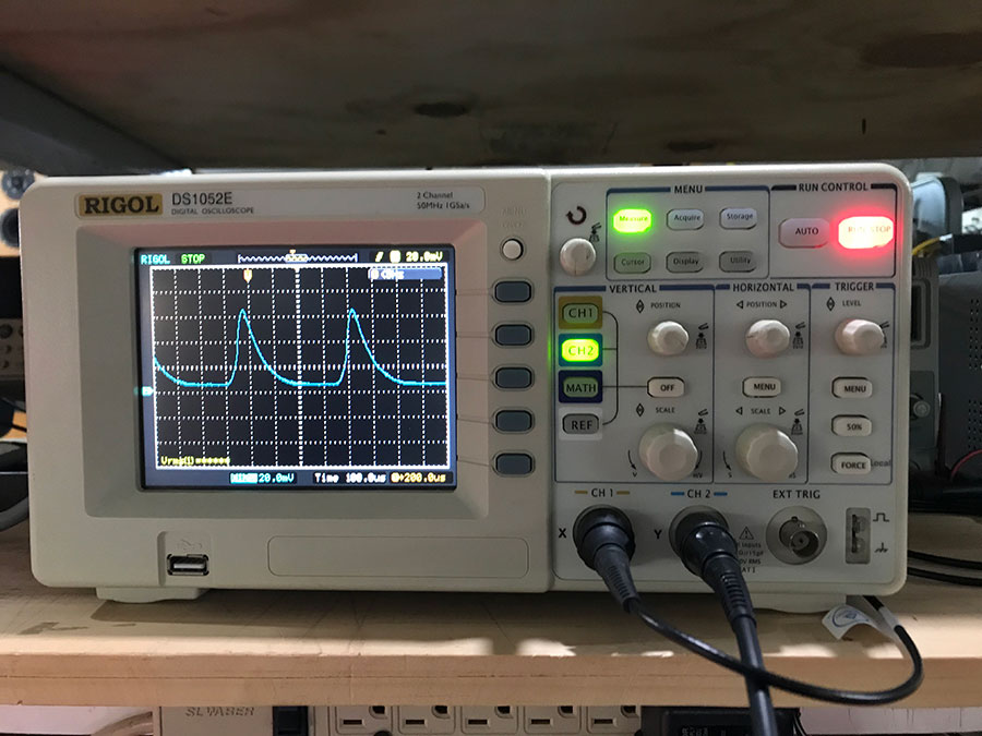
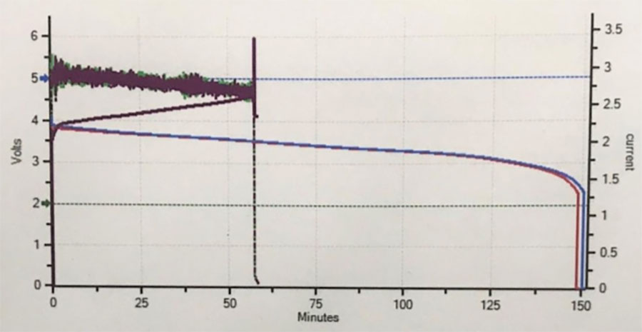
The battery energy storage system has been studied experimentally for over 150 years. Battery cell integrity and electrical charge parameters are investigated using high-speed voltage capturing technologies in combination with induced loads designed to push the limits of the storage capabilities of the battery and its environmental casing. The monitoring software takes observations hundreds of times per second to show the resultant voltage current waveforms revealing the dynamic performance improvements over standards for the industry. When the specialized impulse voltage current waveform is initiated there are several unique current flows occurring; electrolyte ion current, electrode plate electron current, and a charge transfer reaction current. The constantly reversing sharp magnetic gradient creates an abrupt electron current reverberation signature ringing within the battery environment. This non-linear, asymmetric, Dirac Sea gate is triggered by the hysteresis of the relationally large ion current to the extremely small electron current. This time delay between the two differing ion masses regauges the system potentials to a significantly higher platform acknowledging the open system. Improved voltage and current storage parameters are observed while reducing the typical thermal response of the battery cell.
Keywords: cell integrity, environmental casing, current waveforms, ion current, electron current, magnetic
gradient, charge transfer reaction, asymmetric environment, Dirac Sea, hysteresis, open system
_________________________________________________________________________________
1. Introduction
Exceptionally complex technologies have been developed to monitor battery charging processes in the hopes of finding solutions to improve charge performance. Society has become more dependent on electric vehicles and the electric-based technologies all around us, however our fragile distributed power network leaves us vulnerable.
K. Zimmer
Dramatically improving battery storage capabilities is now critical to our society’s basic infrastructure needs.
The process of charging battery plates in an electrolyte, storing that capacity, and then discharging it, is considered to be a straight forward chemical reaction. Typically there is a flow of metal ions through an electrolyte, the terminal plates are either gaining a charge from a connected external source or releasing that stored charge to an external load. The loss of electrolyte due to terminal heating and the structural degradation of the terminal plates is observed to be standard for this common procedure. The battery’s charge capability is at its maximum potential when it is new and that value degrades with each charge/discharge cycle throughout its useful life. Each of these four statements, though typical for normal battery charging technology, they do not rigorously apply to the unique impulse charger designed by Miller.
What appears to be a simple chemical reaction (during charging) turns out to be a constantly improving (up to a point) energetic phase change state. Instead of just one ion flow there are numerous, though this paper will only focus on three. A traditional charger heats the electrolyte 20 to 40 degrees F over ambient but with the impulse-charged environment, the electrolyte can be cooler than ambient by 1 to 2 degrees F. The battery terminal plates do not appear to degrade and breakdown but their performance shows that the may actually be improving structurally. With each of the hundreds of test cycles observed by this author the storage voltage improved to better than new and charge cycle times were reduced. The charge environment technologies that this paper covers has shown very positive improvements in battery life with storage potential increasing over time instead of decreasing. This results in longer battery output runtimes with decreased battery costs over the life of the battery. The idea of time, from a quantum perspective, will also be addressed as part of the overall energy improvement equation. The specific impulse that is used raises the battery charging environment from traditional electrochemistry up to a quantum phase change state with improved energetic properties.
2. Overview of battery testing
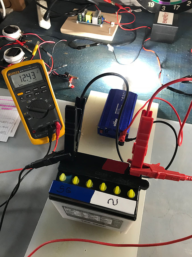
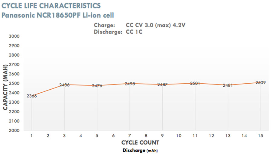
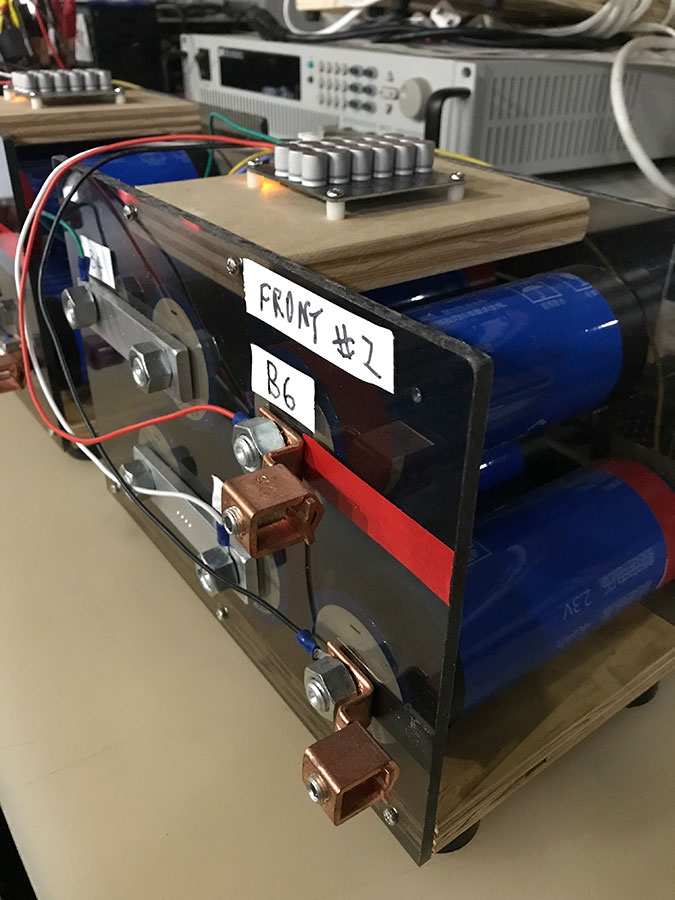
Reviewing the Miller battery testing at EBL throughout all of 2019 through February 2021, this author has seen numerous charge/discharge anomalies that do not fit the expected classical battery chemistry results. Several of these unique outcomes are outlined below. The range of batteries tested: the Panasonic NCR18650 lithium, Rolls Surrette S6 L16-6, Duracell SLA 12V 80Ah AGM, andImpulse Circuit proprietary hand-built nano graphene batteries. The computerized battery analyses hardware and software are the West Mountain CBA IV Pro 150 watt and 2000 watt units.
Viewing more than 300 test cycles of numerous battery types of varying material compositions and reviewing the test data from over 3,000 test cycles, there
were no perceptible declines in any of the batteries electrical performances, only battery storage improvements were observed. There were no physical distortions of the outer casings due to swelling or overheating. The batteries’ surface temperatures remained at ambient room temperature. In contrast, batteries being charged with standard battery chargers showed a loss in storage capacity, the outer casing surface temperatures rose, the physical casings swelled, and output decreased over the same timeframes of the Miller impulse charger. Listed next are some of the basic observable performance improvements viewed with this new charging method.
Unique Performance Indicators
- Total availability of the battery’s input of volt/amps (watts) increases over time; the battery is able to accept a higher input of watts.
- Battery’s surface temperature stays ~ 1 degree cooler than room temperature during impulse charging.
- Battery holds a greater maximum storage charge over standard for a longer period of time.
- Battery’s charge-time cycle decreases to reach that maximum storage charge.
- Battery’s output of volt/amps (watts) increases over time, more work in watt/ hours, can extracted for each discharge cycle, up to a leveling off point.
- Battery’s surface temperature stays cooler than room temperature during discharge.
3. Ion momentum overcharge mechanism
What causes these unique observable anomalies? It’s the specific impulse that their charger generates. It triggers numerous ion flows within the battery environment, as well as unique energetic exchanges external to the battery.
K. Zimmer
This unique impulse charge creates internal environmental characteristics that are far beyond the simple flow of the electrolyte’s ions and charge electrons moving from one terminal plate to the other. There is a world of change taking place unique to this impulse battery charging technology. Pulling from Bearden , Vincent , and Bockris 1 2 3, there are a minimum of three types of current flows in a typical lead acid battery. The electrolyte has its ion current (1), the terminals and the electrode plate material have their electron currents4 (2), and the junction of where the electrolyte interfaces with the battery plates there is a “charge transfer reaction” current (3). Bearden, Vincent, and Bockris describe the battery environment of having even more currents than just those three mentioned above, along with numerous non-linear processes taking place (showing time reversal effects), all this occurring when a specific charge impulse is introduced5. Our battery charging system uses a proprietary version of a unique charge impulse that creates these observable effects.
Let’s take a closer look at a simplified version of just two of the ion flows in a battery during our special charge cycle. Using the example of the electrolyte’s lead sulfate ions and the electrons of the electron current, the size and charge of the lead sulfate ion is massive (by many thousand fold) when compared to the charge electron’s size/charge. Both ion and electron are not only flowing from one terminal to the other as dictated by charge flows, but they are also being vibrated very quickly by the charge process. Though the electron current is what powers the load during discharge, it’s the action of the lead ion current of the electrolyte that
reveals where the overpotential of this circuit comes from. Internally, both the ion and electron flow need to reverse direction with each impulse reversal. The electron
1 T. E. Bearden, Matters Arising, Original papers published in 1999, Energetic Productions, 2020.
2 Colin A. Vincent, Modern Batteries: An Introduction to Electrochemical Power Sources, Edward Arnold Publishers, Ltd., London, 1984.
3 J. O’M. Bockris, “Overpotential, a lacuna in scientific knowledge”, Journal of Chemical Education, 48(6), June 1971, p. 352-358.
4 https://chem.libretexts.org/Bookshelves/Analytical_Chemistry/Supplemental_Modules_(Analytical_Chemistry)/
Analytical_Sciences_Digital_Library/JASDL/Courseware/Analytical_Electrochemistry%3A_The_Basic_Concepts/
03_Fundamentals_of_Electrochemistry/A._Electrochemical_Thermodynamics/02_Electrical_Double_Layer_and_Charging_Current
5 T.E. Bearden, Matters Arising, Original papers published in 1999, Energetic Productions, 2020.
Impulse Circuit
changes direction instantaneously whereas the much larger ion takes some time for that reversal. The time gap between the two differing charge reversals is important.
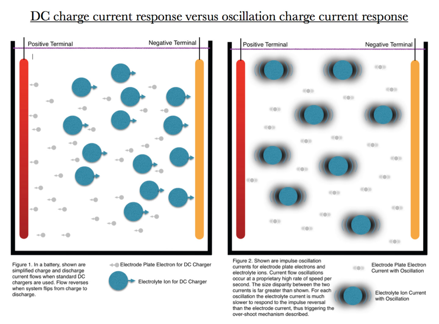
Consider the mass, charge and momentum of the lead sulfate ions as they are being resonated many times per second. This is not a simple vibratory pulse, but a specific current impulse pushing these ions back and forth with considerable force. With every vibratory cycle this large lead sulfate ion must come to a near complete stop, reverse direction, accelerate rapidly, and again come to a near complete stop. Repeat. Repeat. Repeat. At each end point of the vibratory cycle the ion over-shoots its mark (compared to the electron) due to its mass and momentum . This over-shoot is key to understanding this mechanism. 6 [Please note that current classical electro-magnetics does not consider the interaction with the active vacuum to be of any significant consequence. Even though decades ago
6 T.E. Bearden, Back-Popping a Two-Current Lead-Acid Battery. http://www.cheniere.org/misc/battery%20poppers.htm
K. Zimmer
particle physics has proven that every electrical circuit continuously interacts with the vacuum field as part of its energetic operation.] Remembering Lenz’s law, with every sharp change of direction of the ion there is an induced emf creating a polarized force that is opposed to that direction of flow. The over-shoot of this ion flow creates a sharp electrical gradient as it changes directions during each of these vibratory cycles, of which there are many per second. This “just created” excess and unique energy is picked up by the electrolyte’s environment and is deposited on the cells’ plates as a new usable energy source. There is a different spin, organization, and signature to this “newly minted” energy. It not only appears to pack more tightly onto the plates but it has specific organizational qualities unique to this form of structured energy.
4. The Dirac Sea as viewed from the vacuum of space
It is believed that there is an actual structural surface change at the plate surface interface with the electrolyte that accounts for some of the effects seen in the lab. It is understood that this induced ionic pumping triggers an asymmetrical source phenomena that pulls on the vacuum of space (the Dirac Sea) gathering in excess energy freely available to it . The oscillation of the 7 lead ions, with its time delay response from the urging of the changing magnetic field, is actually creating an energy gate. The dipole of the lead ion is being regauged, having its potential moved vigorously while in oscillation. As the applied magnetic field reverses, the battery environment experiences a sharp gradient or charge event. Almost simultaneously, the lead ion overshoots its point of direction change due to its large mass/charge and the magnetic field reversal. This creates an energy vacuum allowing it to absorb new environmental energy from the Dirac Sea8. This flow stabilizes the energy gradient depositing it into the battery plate environment and electrolyte. This is how they explain the ion momentum overcharge mechanism.
7 T.E. Bearden, Vacuum Contributes Excess Energy to Battery and Circuit. https://bibliotecapleyades.net/Ciencia/secret_projects/ project096.htm
8 T.E. Bearden, Ibid. Impulse Circuit
5. Conclusion
This discussion over-simplifies the actual cross-sectional charge transfer taking place in a battery while being charged with Miller’s unique impulse technology. The very environment of the battery goes through a sea-change improving its performance characteristics to more of an energetic gate allowing continuous flow into and out of the battery simultaneously. The understanding is that the charging mechanism shuttles these unique current potentials throughout the battery storage system in new and unique ways yet to be fully understood.
The impulse is key. Dirac points out, “a perturbation will cause transitions from states with E positive to states with E negative.” “The 9 sharp impulse gradient of positive energy pops out negative electrons from the Dirac Sea, leaving Dirac Sea holes which are negative mass energy electrons.”10 These negative-energy EM fields are the source of the negative energy entering the system causing the cooling reaction and improving the charge density onto the battery plates.
The impulse wave itself operates along the x-, y-, and z- axes, and freezes momentarily at the point of oscillation reversal, then only the t- axis (time) is available for energy transfer11. That time/energy is polarized (moving in two directions along the same path, as in a double helix) in time/space making it an electrogravitational wave that hits the electrolyte’s ions and is then carried to the battery’s cell plates. When the Miller impulse charging system is repeated with enough frequency, the battery plates slowly become non-linear due to the harmonics and subharmonics of the impulse in the battery environment. This continued pulsing and echoing creates a wave-to-wave interaction (instead of just absorption and emission of radiation) setting up time polarized EM waves with the local Dirac Sea. Time energy is transduced into excess spatial negative mass energy, that emits negative-energy EM fields deposited on the battery plates12. This open system interaction does not violate any conventional conservation of energy laws and it explains the broken charge symmetry repeatedly seen with Miller impulse battery charger technology.
9 Dirac, Proceedings of the Royal Society A, Vol. 117, p.610.
10 T.E. Bearden correspondence, http://www.cheniere.org/correspondence/011409.htm
11 T. E. Bearden, Matters Arising, Original papers published in 1999, Energetic Productions, 2020.
12 T.E. Bearden, Ibid.
K. Zimmer
“The first principles of things will never be adequately known. Science is an openended endeavor, it can never be closed. We do science without knowing the first principles. It does in fact not start from first principles, nor from the end principles, but from the middle. We not only change theories, but also the concepts and entities themselves, and what questions to ask. The foundations of science must be continuously examined and modified; it will always be full of mysteries and surprises.”
– A. O. Barut, Forward, ”Debating the Final Theory,” Foundation of Physics 24(11), Nov. 1994, p. 1571. [http://fs.unm.edu/Quantization.pdf , http:// www.cheniere.org/techpapers/bearden4.pdf ]
“The experiment determines the validity or invalidity of the theory, not vice versa.”
– T.E. Bearden, Matters Arising, p. 290.
“…the scientist, seldom if ever is he aware of the eternally problematic character of his concepts…he sees them as immutably given…not seriously to be doubted… in the interest of science it is necessary to engage in the critique of these fundamental concepts, in order that we may not unconsciously be ruled by them.”
– A. Einstein, quoted from his introduction to Concepts of Space: The History of Theories of Space in Physics, by Max Jammer (2nd Edition) Harvard University Press
Copyright© March 2021, Karl Zimmer, All rights reserved